Preparation work:
1, connection (chuck connecting disk, cylinder fixed seat, pull rod)
Chuck flange
Machine tool spindle can be divided into A type, C type, D type, please make sure the spindle number to purchase or home a chuck connected with reference to machine instructions or manuals. Type A2 for the Taiwan imported hydraulic chuck standard.
Cylinder fixing seat
Pull rod
2, the main components (hydraulic chuck, hydraulic rotary cylinder, hydraulic station)
3, other accessories (joint, foot switch or electric control box)
Chuck rod production
Please follow the hollow rod length calculation
1, tie rod thickness increases to have enough strength. If the rod of insufficient strength will make the fracture and the loss of clamping force, while the workpiece is flying, dangerous.
2, screw loosening is the main reason causing vibration
3, tie rod thickness e as the minimum limit value, the best selection of machining large diameter threaded part F, the E value is the largest possible.
4, to find a strength of 380Mpa (38kg/mm2) above the material to manufacture the pull rod.
5, the thread a, D, f concentricity in 0.05mm within T.I.R.
The installation work
Cylinder connecting plate installation
In order to obtain the numerical above the required, swing hydraulic cylinder connecting plate front end must be a minimum below 0.005mm.
2, when installing the cylinder connecting plate on the lathe back before, should be placed perpendicular connecting disc.
3, must first correction hydraulic cylinder diameter and outer diameter of the connecting plate deflection for the following 0.01mm.
4, the installation of hydraulic cylinder hydraulic cylinder is connected to the disc, tighten the screws as shown below, the more the better as far as possible.
Because the oil pressure cylinder is made of aluminum alloy material, the locking torque about the company hydraulic chuck (same specification screw) 80%
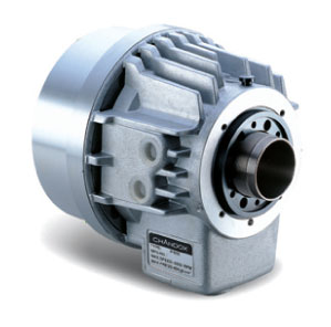
A hollow hydraulic rotary cylinder mounted on
1, the front end of the hollow hydraulic chuck is installed on the spindle, high-speed hollow hydraulic rotary cylinder is arranged on the rear, and the two pull rod to connect to.
2, pay attention to: when the hydraulic cylinder is arranged on the rear of the lathe, lathe protection must be set aside for the vents, so the heat generated by the hydraulic cylinder can be dispersed.
3, hydraulic cylinder connecting plate edge correction of deflection and hydraulic cylinder connecting plate diameter runout within 0.005mm, excessive deflection will cause vibration, short service life caused by hydraulic cylinder records.
4, in the hydraulic cylinder is mounted on the lathe spindle bracket distance closer place is better, and the hydraulic cylinder installation connecting plate and measured deflection are in the table below show.
5, must be installed on the countersunk head screws to prevent loose connection plate.
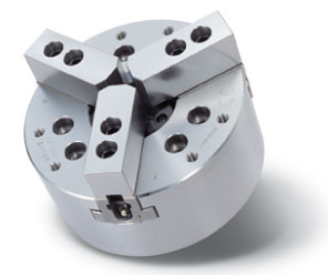
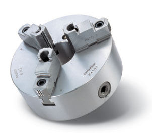
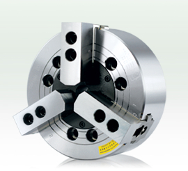
Hydraulic chuck (hollow) installation steps
1, the pull rod is arranged on the rotary cylinder. Screw rod and rotary cylinder piston screw, until the end of the piston. (if not reach position will damage the piston screw stop lock).
2, the rotary cylinder is arranged on the main shaft (rotating cylinder connecting plate), check the rotary cylinder with no deflection and pipe is normal, set the oil pressure to low pressure (0.4Mpa-0.5Mpa, 4-5kgf/cm2), so that the piston 2-3 times after parking in the front, then turn off the power.
3, the installation or remove chuck, need to use a harness or rings fixed (8 "below the chuck is not attached to the rings).
4, use remember rings or sling removed from the chuck.
1, the installation chuck to pull rod. Soft claw and the dust under the cover of chuck, with 1,2,3 screws into the number of teeth will socket wrench in chuck center hole, pull rod nut lock into the pull rod, as the oil is in the 4-5kgf/cm2 position, the pull rod back and forth movement 2-3 times, and the smooth lock nut.
2, pull rod nut lock into the bar, if not locked into a smooth, should be re examined the screw thread center is inclined... And so on, such as mandatory lock will cause the error and precision of screw thread damage.
Chuck installed on the main shaft. Turn the socket wrench to security combined with the spindle end. According to the following sequence of lock screw
Note: Chuck screw connection, click set torque locking. If the locking torque is insufficient or too will result from the accident.
The attachment screw for the use of principle, if special situation please use the above 12.9 (M22 10.9) and have enough length.
Use a socket wrench to adjust the tension wheel position adjustment plate, with the main body of 0.5mm-1mm clearance, when base claw in the beginning.
Install the dust cover and deflection detecting chuck. The chuck edge and end swing in 0.02mm.
Hydraulic chuck installation notes
1, when changing a joint part, tooth type and T type nut must clean up the basic jaws, otherwise it will cause the accuracy of No.
2, in accordance with the shape of workpiece and cutting conditions to set the hydraulic pressure, if the tubular workpiece by high voltage clamp will cause deformation.
3, clamp casting workpiece holding surface or conical, special claw used with dentate clamping surface of workpiece material, not flying.
4, the clamping eccentric workpiece material, the effects of centrifugal force eccentric weight in a single claw, processing to use low speed.
5, can not be used with the base claw rows of teeth is not above claw, denticity is insufficient, will affect the clamping force and precision, serious damage to the base jaw.
Before 6, the operation began, the use of low speed at once, check the position of the object and a workpiece and tool, the tool seat interference.
7, if the length of the workpiece clamping, the use of the tailstock center supports the other end or.
8, long time holding machine, chuck can not clamp the work.
9, when the improper operation or mechanical failure caused by tool or cutter base hit chuck, immediately stop check up, base claw, T block, connecting screws and accuracy of clamping is normal.
10, the height of a special use hydraulic pressure to a lower than standard.
Circuit design of rotary hydraulic cylinder
1, hydraulic circuit
NEWS CENTER
Home > News Center

Show News
Installation steps to hydraulic chuck
Date:2014-04-16 21:12:24


