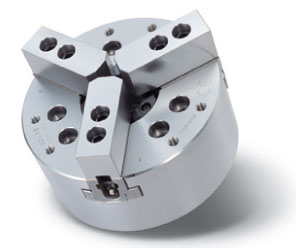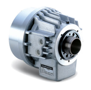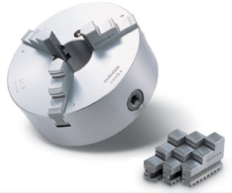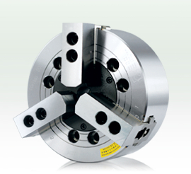
Hydraulic chuck (hollow) installation steps
1, the pull rod is arranged on the rotary cylinder. Screw rod and rotary cylinder piston screw, until the end of the piston. (if not reach position will damage the piston screw stop lock).2, the rotary cylinder is arranged on the main shaft (rotating cylinder connecting plate), check the rotary cylinder with no deflection and pipe is normal, set the oil pressure to low pressure (0.4Mpa-0.5Mpa, 4-5kgf/cm2), so that the piston 2-3 times after parking in the front, then turn off the power.
3, the installation or remove chuck, need to use a harness or rings fixed (8 "below the chuck is not attached to the rings).
4, use remember rings or sling removed from the chuck.
The installation graph {chuck, chuck installation diagram 2}
5, the installation chuck to pull rod. Soft claw and the dust under the cover of chuck, with 1,2,3 screws into the number of teeth will socket wrench in chuck center hole, pull rod nut lock into the pull rod, as the oil is in the 4-5kgf/cm2 position, the pull rod back and forth movement 2-3 times, and the smooth lock nut.
6, pull rod nut lock into the bar, if not locked into a smooth, should be re examined the screw thread center is inclined... And so on, such as mandatory lock will cause the error and precision of screw thread damage.
7, installed in the spindle chuck. Turn the socket wrench to security combined with the spindle end. According to the following sequence of lock screw
Chuck 3 installation diagram
Note: Chuck screw connection, click set torque locking. If the locking torque is insufficient or too will result from the accident.
The attachment screw for the use of principle, if special situation please use the above 12.9 (M22 10.9) and have enough length.
Use a socket wrench to adjust the tension wheel position adjustment plate, with the main body of 0.5mm-1mm clearance, when base claw in the beginning.
Install the dust cover and deflection detecting chuck. The chuck edge and end swing in 0.02mm.
Figure 3

